Simplified Model Definitions
The so-called theory module contains the basic tools necessary for decomposing the input model (either in LHE or SLHA format) into simplified model topologies and using the output of the decomposition to compute the theoretical prediction for a given experimental result.
The applicability of SModelS is currently restricted to models which contain a Z2 symmetry (R-parity in SUSY, K-parity in UED, …) and result in a missing transverse energy (MET) final state at experiments. This is required in order to provide a clear structure for the simplified model topologies appearing during the decomposition of the input model. Below we describe the basic concepts and language used in SModelS to describe the simplified model topologies.
Elements
A simplified model topology representing a specific cascade decay of a pair of BSM states produced in the hard scattering is called an element in the SModelS language. Elements contain the final states (Z2-even) particles appearing in the cascade decay as well as the masses of the BSM (Z2-odd) states which have decayed or appear in the last step of the decay. A representation of an element is shown below:
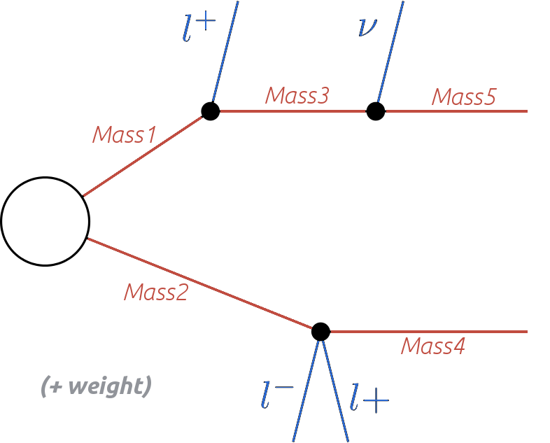
An element may also hold information about its corresponding weight (cross section times branching ratio times efficiency). [*] The overall properties of an element are illustrated in the scheme below:
SModelS works under the inherent assumption that, for collider purposes, all the essential properties of a BSM model can be encapsulated by its elements. Such an assumption is extremely helpful to cast the theoretical predictions of a specific BSM model in a model-independent framework, which can then be compared against the corresponding experimental limits. For instance, as shown in the scheme above, only the masses of the BSM states are used and other properties, such as their spins or other quantum numbers are ignored (the PID’s are, however, stored for book-keeping).
Below we describe in more detail the element properties and their implementation in SModelS.
- Elements are described by the Element Class
Vertices
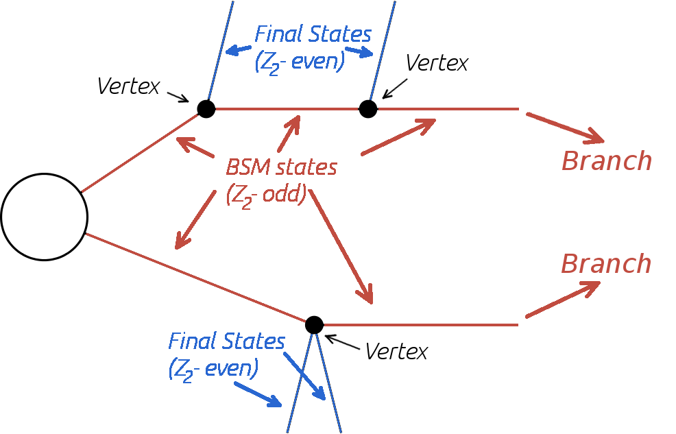
Each Z2-odd decay is represented by a vertex containing its final states (one Z2-odd state and the Z2-even particles), as shown in the scheme above.
Final States (Z2-even)
Final states indicate all Z2-even states coming out of a vertex (see scheme above). In most cases, these correspond to Standard Model particles (electrons, gauge bosons, Higgs,…). Note that, if the input model contains BSM states which are Z2-even (such as additional Higgs bosons), these also appear as final states. In contrast, stable or long-lived Z2-odd particles which might appear in the detector (either as MET or charged tracks) are not classified as final states.
- Z2-even states are defined (and can be easily modified) in
particles.py
Intermediate States (Z2-odd)
The Z2-odd states are always assumed to consist of BSM particles with Z2 conserving decays of the form: (Z2-odd state) \(\rightarrow\) (Z2-odd state’) + final states. The only information kept from the intermediate states are their masses (see scheme above). If an intermediate state is stable and neutral, it is considered as a MET signal.
- Z2-odd states are defined (and can be easily modified) in
particles.py
Branches
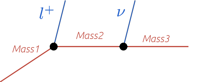
A branch is the basic substructure of an element. It represents a series of cascade decays of a single initial Z2-odd state. The diagram below illustrates an example of a branch.
The structure of each branch is fully defined by its number of vertices and the number of final states coming out of each vertex. Furthermore, the branch also holds the information about the particle labels for the final states coming out of each vertex and the masses of the intermediate states, as shown below.
- Branches are described by the Branch Class
Element Representation: Bracket Notation
The structure and final states of elements are represented in textual form using a nested brackets notation. The scheme below shows how to convert between the graphical and bracket representations of an element:
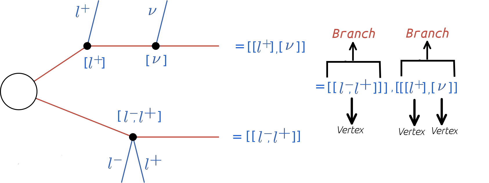
The brackets are ordered and nested in the following way. The outermost brackets correspond to the branches of the element. The branches are sorted according to their size (see element sorting) and each branch contains an ordered list of vertices. Each vertex contains a list of the final states (sorted alphabetically) coming out of the vertex. Schematically, for the example in the figure above, we have:
element = [branch1, branch2]
   branch1 = [vertex1]
      vertex1 = [l+,l-]
   branch2 = [vertex1,vertex2]
      vertex1 = [l+]
      vertex2 = [nu]
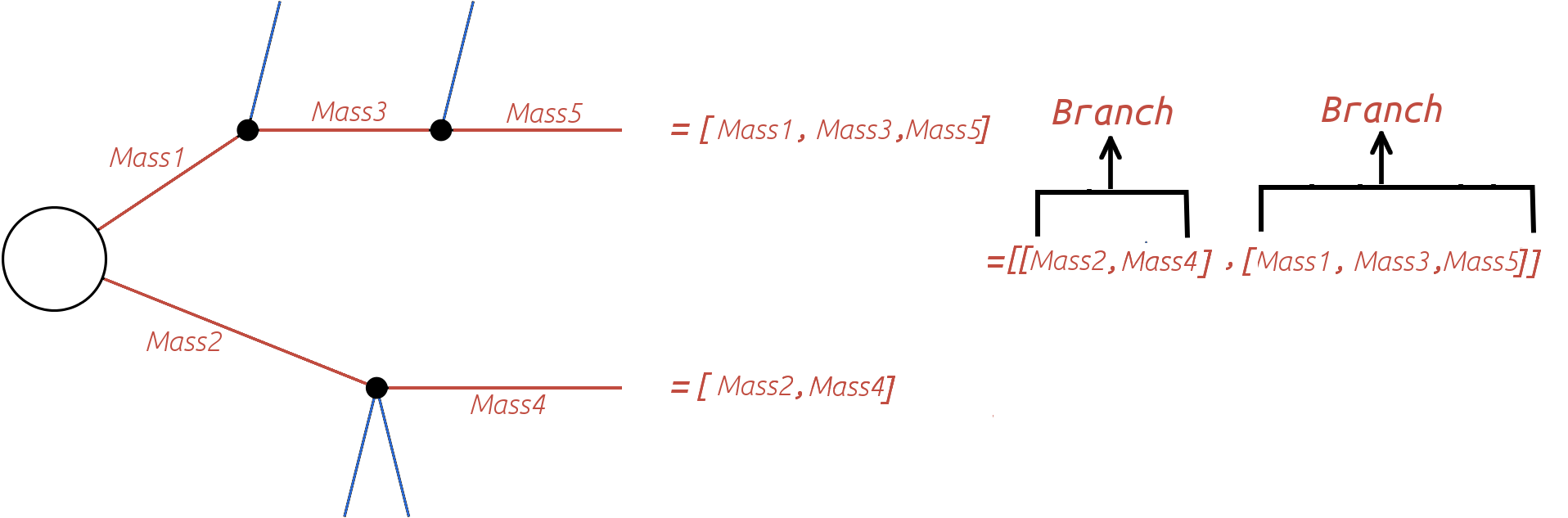
Using the above scheme it is possible to unambiguously describe each element with a simple list of nested brackets. However, in order to fully specify all the information relative to a single element, we must also include the list of intermediate state masses and the element weight. The intermediate state masses can also be represented by a mass array for each branch, as shown below:
Topologies
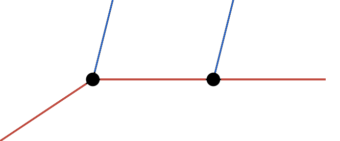
It is often useful to classify elements according to their overall structure or topology. Each topology corresponds to an undressed element, removed of its final states and Z2-odd masses. Therefore the topology is fully determined by its number of branches, number of vertices in each branch and number of final states coming out of each vertex. An example of a topology is shown below:
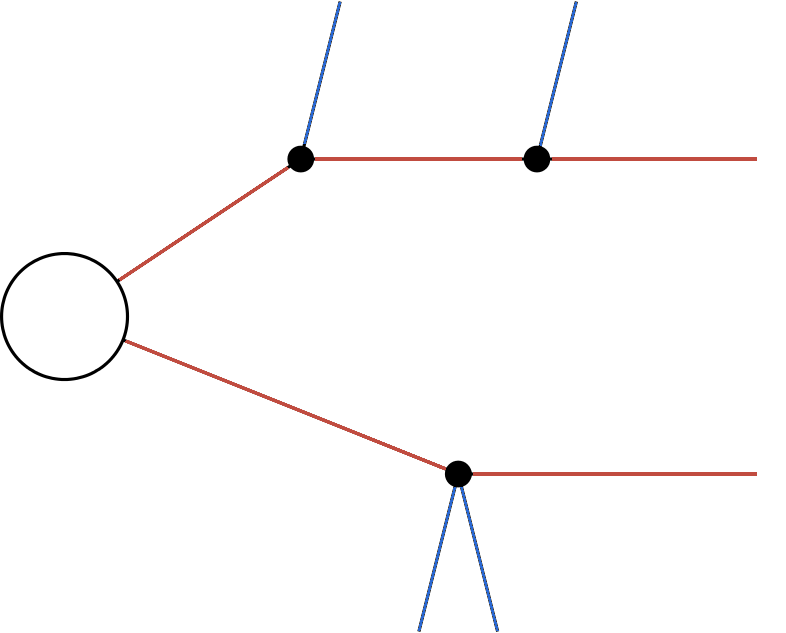
Within SModelS, elements are grouped according to their topology. Hence topologies represent a list of elements sharing a common basic structure (same number of branches, vertices and final states in each vertex).
- Topologies are described by the Topology Class
| [*] | In order to treat the UL and EM map results on the same footing, SModelS applies a trivial binary efficiency to elements for UL-type results as will be explained in detail later. |